Tuesday, May 7, 2013

SWR BRIDGE

Greetings Everyone,

Today we tested a SWR Bridge in our R&D Lab.The SWR Bridge is made by using 6mm toroids winded with 10 turns of 26 SWG copper wire. And also we used 3mm copper tube as shown in figure with wires shorted in two ends. The above circuit is taken from the RF publication issued in 1985. We have only implemented the circuit. The standard SWR's measured are: Zo, Zo/2 and Zo/3.


The below formula is used to measure the SWR:
SWR = (Vforward + Vreverse)/(Vforward - Vreverse)

Schematic diagram is shown below.


 The Results are satisfactory with 7,10 &14MHz Frequencies.

Tuesday, April 16, 2013

13.56MHz ISM BAND AMPLIFIER USING 7NK30Z

Greetings Everyone,

Today we tested an ISM Band amplifier of 13.56 MHz with our standard R.C.T. ,Oscilloscope & Bird 500 Watts Dummy Load. It draws 10A at 33V D.C. That is 330W input and output of 200W. Upon calculating the efficiency more than 60%.

This time we have used a different MOSFET: STP 7NK30Z.  It can withstand up to 7A and maximum voltage of 300V. 7N stands for 7A rating and 30Z for 300V.  


BIRD's 8325 Tenuline Coaxial Attenuator

Greeting's,

First feast your eyes on the pictures below before I explain what this monster machine is.


This is a monstrous 500W, 50 Ohms, 30 dB Attenuator. We got this unit for testing our RF Amplifiers.

The following the specifications for the unit:

Impedance: 50 ohms nominal
Connectors
                  Input    : Bird “QC”, Female N normally supplied
                  Output : Bird “QC”, Female N normally supplied
Power Rating: 500W
Frequency Range: 500 MHz
Attenuation: 30 db ± ½ db, dc-500 MHz
Cooling Method: Dielectric and air convection currents

The Attenuator was tested with our amplifier and we are were exceptionally happy with the results.

The manual for the above unit can be downloaded for further reference from this link: Click Here. 


Friday, April 5, 2013

50 WATTS @ 12VOLTS HF AMPLIFIER USING 16NF06

Greetings to Every one,

We tested another one amplifier in our R&D Lab using 16NF06 mosfet.The results in 14MHz are amazing.We measured 50 watts output in 14MHz and more than 50 Watts in 7MHz using standard test Equipments HP 8920A RCT and GW-INSTEK 30MHz oscilloscope.It drawns 6Amp at 13.8VDC.The efficiency of this amplifier is 60%.  Below is the Photo and circuit details.


Note: T.S Means test select to adjust Minimum 10ma current in each MosFet.

1.) Input Transformer:


This is a step-down transformer. Primary is 4-Turns and secondary is 2-Turns wound on a TV balun core because maximum input power is 5 Watts only 26 SWG is sufficient. We have used 4-Turns primary with 26 SWG and 2-Turns secondary using 24 SWG.

2.) OUTPUT TRANSFORMER:


3.) Output Transformer:

This transformer was constructed using reference from Motorola book (R.F. Device Data -Vol. 2)
Primary consists of single turn copper tube of 4 mm diameter. Secondary consists of 2-Turns of Teflon coated wire.

Here we can see the copper tubes are shorted at one side. TV balun cores are slipped over the  copper tubes and secondary winding is completed last. The primary inductance of one turn copper tube should be 1uH. If the inductance is higher, this amplifier can works at lower frequencies. 

The above picture shows the PCB used to short the two copper tubes.

Here we can see the balun cores slipped over copper tubes.

Regards and Nice Home brewing,
R&D TEAM.


Friday, March 29, 2013

H-Bridge Motor Driver using MOSFET's and Transistors

In this post, we shall be covering on how to construct a H-Bridge Motor Driver circuit using simple MOSFET's and Transistors. The main feature of this H-Bridge is that the motor can be driven in both directions.  

An H-bridge is a circuit that allows a voltage to be applied across any load, like a motor in our experiment, in dual directions. The 'H' here just represents the formation of the circuit and has no reference to anyone.

 The H-Bridge can be realized using simple switches first:-

The H-bridge arrangement is generally used to reverse the polarity of the motor and to let the motor 'free run' to a stop, as the motor is effectively disconnected from the circuit. The following table summarizes operation, with S1-S4 corresponding to the diagram above.

S1S2S3S4Result
1001Motor moves right
0110Motor moves left
0000Motor free runs


 Now let us realize the actual circuit using MOSFET and Transistors:

 To download Schematic: Click Here (JPEG) & Click Here (PDF) 

We have used IRF9540 for P-Channel MOSFET and IRF510 for N-Channel MOSFET. Respective NPN and PNP Transistors are used to drive the MOSFET's which can be seen in the circuit diagram. We have used Arduino to give the logic signals to the pins to turn on and off the MOSFET's. The diodes are provided to prevent back EMF generated by the motor

Direction 1:
Pin1: Logic 1
Pin2: Logic 1
Pin3: Logic 0
Pin4: Logic 0

Direction 2:
Pin1: Logic 0
Pin2: Logic 0
Pin3: Logic 1
Pin4: Logic 1

After reading the above, you  might be wondering why not short the respective PIN's with the same logic. Well you can, that's what we have implemented and its easier to drive the motor in both directions with using only two I/O pins from the Arduino.


 This is the implemented circuit tested in our RnD lab. Below you can see the Working video.
   

Now you can view the motor in slow motion:


Monday, March 25, 2013

LPF (LOW PASS FILTER) FOR 20METER


Greeting's Everyone!!!!!

We built a Low Pass Filter for 20-meter H.F. band which is used in BITX designed by our good friend Farhan (VU2ESE). The inductor coil is made by using 9-turns of 22-S.W.G. on a Teflon former. This L.P.F. worked beautifully and was tested with R.C.T. HP 8920A. We fed only  -7db to take care of mismatch.

Below we have included the picture of the circuit we constructed in the RnD Lab. Also we have included the schematic for home-brewing purpose.


Saturday, March 23, 2013

Communication between two PC’s through the Serial Port:


Hello Everyone,

We set up a half duplex communication between two PC’s through the serial port. The CPU needs a serial port for communicating with each other . To connect these serial ports we need:

  1. Two DSUBSCF female jacks and
  2. Three equal length wires.


DSUBSCF1 Txd (3rd pin) is soldered with a wire to the DSUBSCF2 Rx (2nd pin). Similarly the DSUBSCF1 Rx (2nd pin) is soldered  with a wire to the DSUBSCF1 Txd (3rd pin) and the 5th pin is grounded. Join these two pins with a wire or don't use the pin.  Make sure that all the three wires are of same length. Now your cable is ready, and you can connect the two female jacks to the respective PC’s.Hence they can communicate with each other.

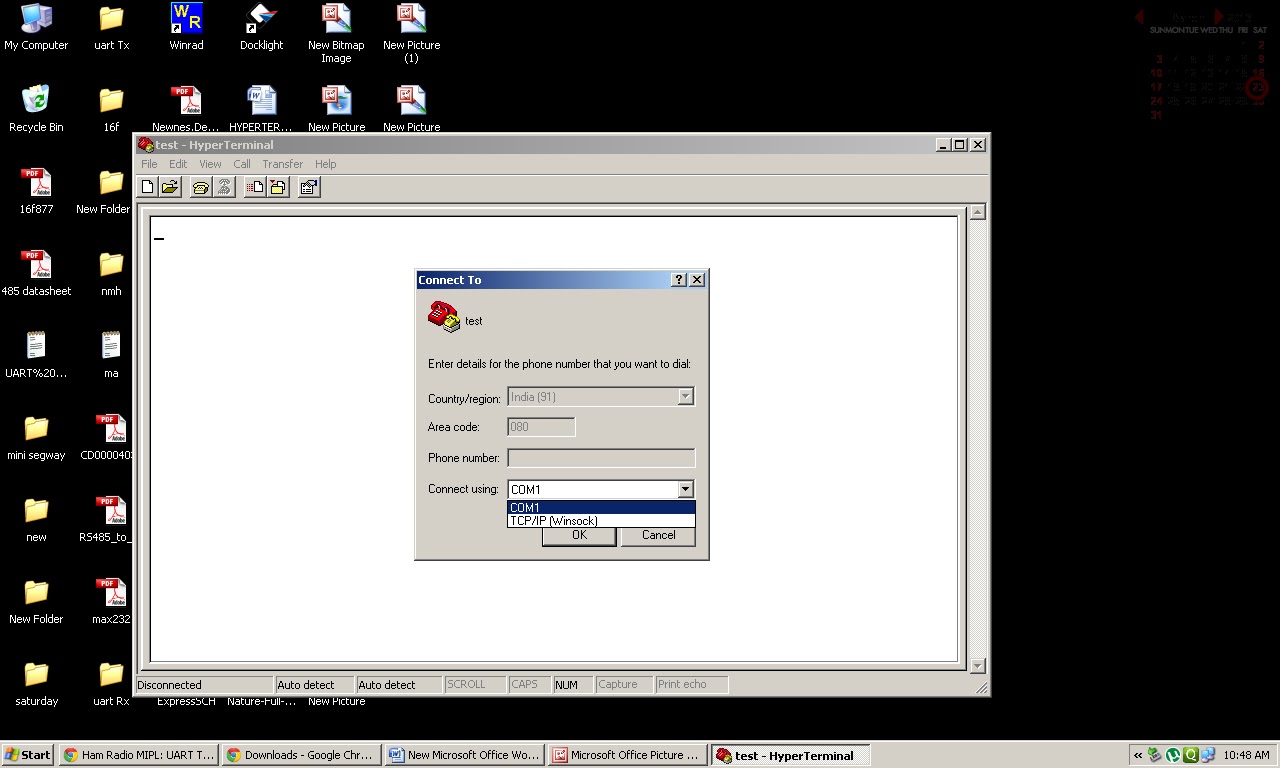
To transmit or receive the data we need to follow few  simple steps which are given below:

  1. Open the Hyper Terminal as shown in the below picture.

     2.  Give any icon name (E.g.:- test).


     3.  Select the communication port as COM1.


     4.  Select the Baud rate or Bits per second as 19200 or 19.2K, Data bits ­­­- 8, Parity - None, 
           Stop bits – 1, Flow control – None. Then click APPLY and later OK.


     5.  Finally you will see the blank screen.


     6.  Follow the same steps from (1 to 5) for the other PC also.


NOTE:For sending the data click on send button, For transmitting click on the BROWSE button and also select any one of the protocol..


For receiving the data follow the same protocol as in transmitting one.


Thursday, March 21, 2013

L.P.F. (Low Pass Filter) for 40 Meter R.F. Systems

Greeting Everyone!!!!!!!!!!!!!

We built a L.P.F. (Low Pass Filter) design published in 1987 ARRL  hand-book in chapter 2 (2-44).
The circuit performs very well in 7Mhz freqency. The ARRL Hand-book has given the test chart as below:

Filter No.
Fco
3 dB
20 dB
40 dB
Max. SWR
C1, C5 (pF)
L2, L4 (uH)
C3
(pF)
87
7.54MHz
8.61
11.5
17.0
1.327
470
1.45
820

This filter works as it is with out any changes and modifications.

Below we have show the tested circuit without any modifications from the original circuit which is also show below.


Wednesday, March 20, 2013

Hyper Terminal using MAX 485


Good evening,

If you want to learn how to run a keyboard and PC with a microcontroller by using the MAX 485. I did a small project (Hyper Terminal using MAX 485). In which the data can be transmitted to the PC through the serial port.

The block diagram of hyper terminal using MAX 485 is given below.


For this we are using a PIC 16F877A with a 4 MHz crystal for oscillating and MAX 485, Since the MAX 485 is to be communicating with the PC, The serial port operates at 12 V, which will fry our MAX 485. To fix this problem we are using MAX 232 as a level convertor. The input of the RS 232 must be TTL or C MOS, so we are using two MAX 485’s. Output Of first MAX 485 is differential output, which is converted to TTL output by using another MAX 485. The signal is feed to PC through the RS 232

The schematic of the Hyper Terminal using MAX 485 is shown below:


The full part list of above circuit is given below:
  •  PIC16F877A                                              
  •  4Mhz crystal                              
  • DB9 connector(female)          
  • DB Hood                               
  • MAX232                              
  • MAX485                                   2                               
  • Capacitor(.01uf)                         2               
  • Capacitor (22pf)                         2
  • Capacitor   (1uf)                         4
  • Capacitor (10uf)                         2
  • Resistors (4.7K)                         7 


UART:

Pic 16F877A has UART (Universal Asynchronous Receiver Transmitter) is one of the basic interfaces which provide a simple and reliable communication between one controller to another controller or between a controller and PC.

Interfacing UART with PIC16F877A

Now we want to display a text in PC from PIC16F877A by using UART module. In PIC16F877A contains a single serial interface that is UART. The Transmitter pins send the data into PC and the receiver pin receives the data from PC. The PC and microcontroller speed are denoted by using baud rate. When the baud rates of both PC and Microcontroller are same, then only the data transmit and receive correctly otherwise not. The TXD (Pin 25) & RXD (pin 26) pins are used for data transmission and receive operation. The UART is initialized and set to 19200 Baud rate, 8 bit, no parity and 1 stop bit. Make sure that the PC settings is also the same

processor pic16f877a
include <p16f877a.inc>
__config _LVP_OFF & _XT_OSC & _WDT_OFF & _PWRTE_ON & _CP_OFF &           _DEBUG_OFF


org 0x00
nop
nop
nop
nop

org 0x05
movlw 0x07         ;turn off the comparators
movwf CMCON

bcf STATUS,RP1
bsf STATUS,RP0
movlw 0x06         ;make all pins as digital i/o ports
movwf ADCON1

bcf TRISC,6 ;enable the Tx pin by clearing it

movlw 0x0c
movwf SPBRG   ;set the baud rate as 19200

movlw B'00100100'
movwf TXSTA ;

bcf STATUS,RP0
movlw B'10010000'
movwf RCSTA
main
movf PORTA,0         ;read the port A pins
movwf TXREG ;transfer the data into the register
bsf STATUS, RP0
here
btfss TXSTA, TRMT ;check whether data is transmitted to Tx pin
    goto here                         ;if no goto here
    bcf STATUS, RP0
clrf TXREG                 ;clear the register
goto main                 ;repeat the loop
end


Here initializing the PIC is very important. For UART turn OFF the comparator and make all analog ports as digital port by the using the register ADCON1.make sure that the PORTC TX pin is low and Rx pin to high for data transmission and receive. The baud rate is selected by SPBRG resister.
The TSR plays a major role in data transmission. The read data from the PORT A is send to the TXREG by using the software. Once the data was send to MAX 485 the TRMT bit will be set. Unless the data is not sent the TRMT bit is zero.
The input is given through the switches, the binary value is given as input which is displayed in the PC as a ASCII value
For example
When the input is: 00111101
The output is:         9
Similarly to get the different output varies the input binary value by switching ON & OFF of Port A input pins.   


Wednesday, March 13, 2013

250 WATTS PUSHPULL RF AMPLIFIER


    Dear all,

               We are very happy to share this experimental result. That is we tested a 250watts rf amplifier in     our R&D lab.This amplifier is made with 10nos of  irf 510 mosfets. .Due to insufficient
power supply we got 150 watts only at 29volt 9ampere DC.  The rf input is 5Watts at 13.56MHz ISM band. We need 33volts at 15amperes and we are awaiting this power supply. Final result  and brief about this we shall publish after testing with  high voltage and high current power supply.

Regards
R&D team.