Tuesday, March 18, 2014
Saturday, March 15, 2014
Bootloading/Burning hex file to Atmega328 using Parallel port
Dear all,
While working using arduino, Bootloader has crashed, we came with the solution for bootloading/burning hex file into Atmega328 without arduino using icsp pins in microcontroller and parallel port. we have taken the circuit and explanation from avrprogrammers.com.
Here is a solution for Bootloading/programming Atmel atmega328 uisng ICSP pins.
Connect the atmega328 pins(MOSI, MISO, SCK, RESET and GND) as shown in schematic, power up the circuit with five volts. To do this I have used the ISP Programmer 1.2.0.56.
For software click here.
Here is the procedure for using this software:-
Monday, March 10, 2014
VXO
Dear all,
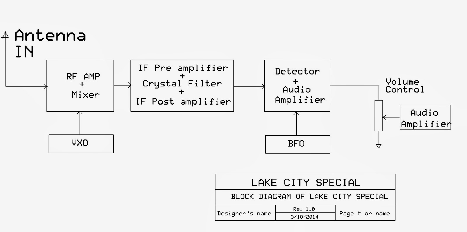
We wanted to make a simple solution for Lake City Net
operating at 7085KHz daily between 8:15Am and 8:30Am. We have chosen IF as
4915KHz for which standard low cost crystals are available. This requires a LO
of RF+IF=12MHz, We have happily configured a 12MHz VXO. This VXO fortunately
covers 11995KHz also giving rise to coverage of CHARMINAR NET operated at
7080KHz daily until 8Am. Below is picture of experimental VXO and the table
contains test result.
Different values of the crystal with different capacitor in X position
Friday, March 7, 2014
Monday, March 3, 2014
Wednesday, February 26, 2014
Tuesday, February 25, 2014
Friday, February 21, 2014
MPPT CHARGE CONTROLLER
Dear all,
Here we are with Arduino based MPPT charge controller.This project
is inspired from Mr. Tim Nolan’s Arduino MPPT. We can share this as long as we mention
his website link.
Here is the link: Click here
The display part is taken from the KIBI: Click here
We didn’t use Tim Nolan’s hardware as we wanted to be different and simple (No MAX IC’s).
Our circuit diagram is given below:
We tried to make the circuit using IRF5210 because of high
input capacitance we shifted to IRF9540. We used instrumentation amplifier TL082
to amplify the solar current. To generate –ve voltage required for TL082 we used
555timer and lm7905 for -5volts generation Modification in the software:
We modified the code so that PWM is around 20 KHz and our
MOSFET’s are happy at this lower speed.
For your reference this is the link for Mr. Tim Nolan’s
circuit:
Click hereSaturday, February 15, 2014
DC DC CONVERTER FIELD TEST
We have
tested the DC DC converter in field yesterday in SALEM. The two units are
working more satisfactorily than we expected. We connected two solar panels of
100Watt in series to get the 40Volts on no-load and 36Volts on load (Battery). The
test is continued till the shade falls on the panels at 5:30. For 2hrs the battery
gets fully charged.
Improvements
in the 2nd unit:-
There
was a high frequency humming sound in the transformer. To reduce that we
increased the turns ratio from 7:5 to 8:6. We added two high voltage capacitors
(1000uF & 0.1uF) at the input to remove spikes. We relocated the diode to
improve the heat dissipation. The MOSFET and Diodes are placed in the front and
back panel respectively. The raise in temperature of panels is less than the
previous unit.
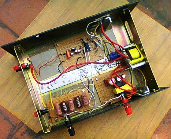
The pictures
of 2nd unit are given below.
The schematic
diagram is shown below.
For more details please feel free to contact us.
Friday, February 7, 2014
Subscribe to:
Posts (Atom)


.jpg)