
Hello Everyone....
We have made a new progress in the RnD Labs today with a new experiment, to learn and to use in our daily electronics conquests.
We successfully completed an Analog - Digital converter using the PIC family micro-controller PIC16F88. The datasheet provided, has a very good explanation of the setup process and I promise you that it will take a good amount of time and patience to read, study, rig-up a circuit, test the circuit, write the program and then debug it and finally you will end up having a working ADC. Well all this because your doing it for the first time and hence I have provided you in this post the code that we have made/coded to get the ADC working. All the details to setup the ADC using 16F88 is below. Keep following.
The datasheet for the PIC16F88 can be found in this link: Click Here
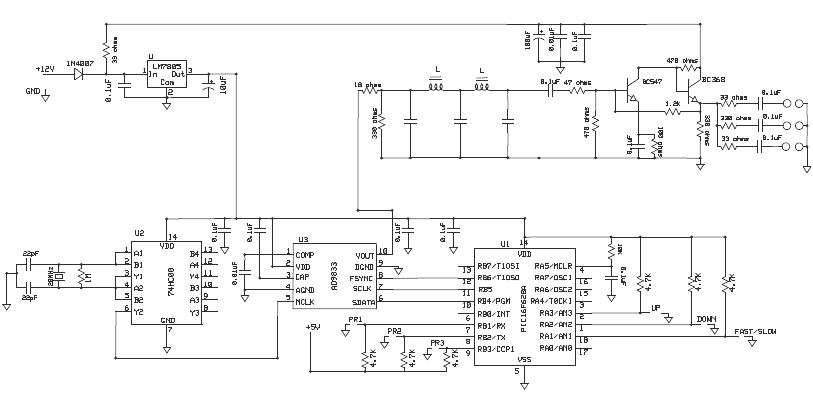
Firstly, let us setup the circuit and test it: Here is the circuit and the JPEG download of the circuit: Click Here.

Some debugging tips for the circuit. Mainly, check the orientation of the 78L05 regulator as here you will be varying the voltage and a wrong orientation will lead to the device to fail. Also, check the potential voltage divider ratio which is why we have used a 100K and a 5K resistance in our experiment.
Now let us come to setting up the ADC and program. Below are the mentioned steps to setup the ADC in the software.
The PIC16F88 as an ADC and an Internal Oscillator which we shall be mainly using the experiment. 16F88's ADC has the following registers to be setup:
• Analog Select Register (ANSEL) - Bank 1
• A/D Control Register 0 (ADCON0) - Bank 0
• A/D Control Register 1 (ADCON1) - Bank 1
The result of the ADC/digital output is stored in two registers based on the Right or Left justified bit. They are:
• A/D Result High Register (ADRESH) - Bank 0
• A/D Result Low Register (ADRESL) - Bank 1
These steps should be followed for doing an A/D conversion:
1. Configure the A/D module:
• Configure analog/digital I/O (ANSEL)
• Configure voltage reference (ADCON1)
• Select A/D input channel (ADCON0)
• Select A/D conversion clock (ADCON0)
• Turn on A/D module (ADCON0)
2. Wait the required acquisition time.
3. Start conversion:
• Set GO/DONE bit (ADCON0)
• Wait the required acquisition time.
4. Wait for A/D conversion to complete, by either:
• Polling for the GO/DONE bit to be cleared
5. Read A/D Result register pair (ADRESH:ADRESL)
6. For next conversion, go to step 1 or step 2 as required.
The A/D conversion time per bit is defined as TAD. A minimum wait of 2 TAD is required before the next acquisition starts.
Although, if you still feel the above steps are little hard to follow, try to download the source code (ASM) given below which has the comments.
ADC source code : Click Here (ASM)
ADC flash file : Click Here (HEX)
ADC full Project : Click Here (ZIP)
We have made a new progress in the RnD Labs today with a new experiment, to learn and to use in our daily electronics conquests.
We successfully completed an Analog - Digital converter using the PIC family micro-controller PIC16F88. The datasheet provided, has a very good explanation of the setup process and I promise you that it will take a good amount of time and patience to read, study, rig-up a circuit, test the circuit, write the program and then debug it and finally you will end up having a working ADC. Well all this because your doing it for the first time and hence I have provided you in this post the code that we have made/coded to get the ADC working. All the details to setup the ADC using 16F88 is below. Keep following.
The datasheet for the PIC16F88 can be found in this link: Click Here
Firstly, let us setup the circuit and test it: Here is the circuit and the JPEG download of the circuit: Click Here.

Some debugging tips for the circuit. Mainly, check the orientation of the 78L05 regulator as here you will be varying the voltage and a wrong orientation will lead to the device to fail. Also, check the potential voltage divider ratio which is why we have used a 100K and a 5K resistance in our experiment.
Now let us come to setting up the ADC and program. Below are the mentioned steps to setup the ADC in the software.
The PIC16F88 as an ADC and an Internal Oscillator which we shall be mainly using the experiment. 16F88's ADC has the following registers to be setup:
• Analog Select Register (ANSEL) - Bank 1
• A/D Control Register 0 (ADCON0) - Bank 0
• A/D Control Register 1 (ADCON1) - Bank 1
The result of the ADC/digital output is stored in two registers based on the Right or Left justified bit. They are:
• A/D Result High Register (ADRESH) - Bank 0
• A/D Result Low Register (ADRESL) - Bank 1
These steps should be followed for doing an A/D conversion:
1. Configure the A/D module:
• Configure analog/digital I/O (ANSEL)
• Configure voltage reference (ADCON1)
• Select A/D input channel (ADCON0)
• Select A/D conversion clock (ADCON0)
• Turn on A/D module (ADCON0)
2. Wait the required acquisition time.
3. Start conversion:
• Set GO/DONE bit (ADCON0)
• Wait the required acquisition time.
4. Wait for A/D conversion to complete, by either:
• Polling for the GO/DONE bit to be cleared
5. Read A/D Result register pair (ADRESH:ADRESL)
6. For next conversion, go to step 1 or step 2 as required.
The A/D conversion time per bit is defined as TAD. A minimum wait of 2 TAD is required before the next acquisition starts.
Although, if you still feel the above steps are little hard to follow, try to download the source code (ASM) given below which has the comments.
ADC source code : Click Here (ASM)
ADC flash file : Click Here (HEX)
ADC full Project : Click Here (ZIP)