Greetings,
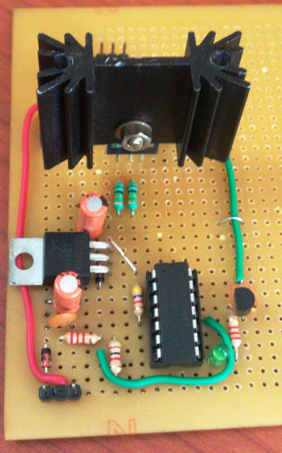
We would like to reveal the secret behind Intelligent Load management and Alarm monitoring Algorithm for 10 KW Solar charge controller.
First of all thanks to the beautiful compiler HIGH TECH C. This algorithm is developed with the help of HIGH TECH C PRO for mid range MCU evaluation version.
The major purpose of this algorithm to manage the load in 15 Amperes per hour.The rated discharge given by customer is 360AH per day. So for 5 days its around 1800 Amperes . We need to limit the discharge in this range so it can work continuously for 5 sunless days.
According to the requirements of our customer we need to develop an algorithm in order to sense the battery voltage and switch the load ON/OFF with the level of voltage from battery.There are so many visible alarms that are present in our system, so its mandatory to produce a warning audible sound for each alarm. This algorithm is capable for doing that also.
Main goals of this algorithm
Part 1.Sense the battery voltage and manage the Load
Part 2.Sense the visible alarms from the system and activate audible alarm and Switch off the audible alarm if reset button is pressed. (Here the audible alarm will be turned off, irrespective of the status of visible alarm)
Check points for Part 1.
1.If the battery voltage is above -51.6 Volts switch On the load.
2.If the battery voltage is below -44.4 Volts switch Off the Load
This is very simple, but need to form a hysteresis loop because when ever it is below -48 Volts it need to shut down the load and need to connect it only after -55.2 Volts. In the same way it can connect load up to a voltage of -48 Volts.
Here we are utilizing the 10bit Analog to digital converter module of PIC16F88 (18 pins) for doing this task.
Check points for Part 2.
1.If the visible alarm is ON, the sensing digital input of MCU will be high. If the alarm is OFF ,then it will be LOW .So according to this sensing I/O pin's status switch ON and OFF alarm. But the tricky thing over here is if user resets the Alarm , audio will be OFF, but still the sensing I/O pin status will be same as the visible alarm status. So here literally we need to sense a transition from LOW state to HIGH state and switch on the alarm.
The algorithm is having 3 functions mainly,
1.For sensing the battery voltage and switching the load- ADC_Function
2.For sensing the LOW to HIGH transition and switch on Audible Alarm-Alarm_Function
3.For Sensing the Reset button press and switch off Audible Alarm-Reset_Function
PROGRAM:-
/*********************************************************************************
* Program for 10KW charge controller
* Intelligent Load Management and Alarm monitoring System *
* Author: Ravi M.D. *
* R&D Engineer, Miconova Impex PVT LTD *
* Date 10/30/2012 *
********************************************************************************/
#include <htc.h>
#define _XTAL_FREQ 8000000 //Set frequency as 8MHz
#define Alarm PORTAbits.RA7 //Assign I/O Pins
#define Signal PORTAbits.RA6
#define Reset PORTAbits.RA0
#define Load PORTBbits.RB4
#define Lower_Voltage 0x015E //Set the voltage ranges here. No need to change in program
#define Upper_Voltage 0x0101
//Internal Clock used at 8MHz
__CONFIG (FOSC_INTOSCIO & WDTE_OFF & PWRTE_OFF & MCLRE_ON & BOREN_OFF & LVP_OFF & CPD_OFF
& WRT_OFF & DEBUG_OFF &CCPMX_RB0 & CP_OFF);
__CONFIG (FCMEN_OFF & IESO_OFF);
unsigned int adc_value,adc_value1;adc_value2=0; //Reading variables for adc higher and lower registers
int i=0; //Variable for switch function
bit out_bit=0; //Bit used for Load ON and off
void Alarm_Function(void); //function to rise alarm
void Reset_Function(void); //function to reset alarm
void main(void)
{
OSCCON=0b01110110; //Oscillator Setting for 8MHz
TRISA=0b01000011; //PORTA configuration
ANSEL=0b00000010; //Only RA1 as analog input
TRISB=0b00000000; //All pins are digital out
ADCON1=0b10000000; //References are VDD and Vss and right justified
ADCON0=0b10001000; //A/D clock as Fosc/2 and channel 1
while(1) //Check infinitely
{
switch (i)
{
/*ADC_Reading for battery management*/
case 0:
ADON=1; //Start ADC Module
__delay_us(100); //wait for acquisition time
GO_nDONE=1; //Start conversion
while(GO_nDONE); //Wait for conversion to be done
ADON=0; //Turn OFF ADC
/*Reading the 10 bit ADC values*/
adc_value1=ADRESL; //Read Lower 8bit registers
adc_value2=(ADRESH<<8); //Read the higher 2 bits and shift it in to 8th and 9th position using shift function
adc_value=adc_value2|adc_value1; //OR both after reading to make a 10bit value
/*Switch ON and OFF load according to the condition*/
if(adc_value>=Lower_Voltage) //Compare with lower voltage range
out_bit=0; //If less than the (here negative voltage so thats why used greater than or equal) lover voltage level, switch OFF load
if(adc_value<=Upper_Voltage) //If greater than the (here negative voltage so that's why used less than or equal) upper voltage level, switch ON load
out_bit=1;
Load=out_bit; //Assign the decision to load.(Important, Its done here to resolve a fluctuation problem)
break;
/*Checking alarm conditions*/
case 1:
ADON=0; //taking precaution by switching OFF ADC and setting the same value as above to the load
Load=out_bit;
Alarm_Function(); //check for alarm condition
Reset_Function(); //Check for reset condition
break;
}
i++; //Iteration variable to exit the switch case and repeat the process
if(i>1)
{
i=0;
}
}
}
Sub Routines:-
1.Alarm_Function:-
#include <htc.h>
#define Alarm PORTAbits.RA7
#define Signal PORTAbits.RA6
#define Reset PORTAbits.RA0
bit flag=0; //flag for identifying the signal transition from 0 to 1
void Alarm_Function(void)
{
if(!Signal)
{
flag=1;
Alarm=0;
}
if(flag&&Signal) //Check whether there is a signal change from 0 to 1 is happening
{
Alarm=1;
flag=0;
}
}
2.Reset_Function:-
#include <htc.h>
#define Alarm PORTAbits.RA7
#define Signal PORTAbits.RA6
#define Reset PORTAbits.RA0
void Reset_Function(void)
{
if(!Reset)
Alarm=0;
}


