Tuesday, December 31, 2013

RF AMPLIFIER 16NF06


Happy New Year Greetings to Every One,

              Today we tested an RF amplifier with 16NF06 mosfet the performance is really superior than IRF510. Normally we used to set 3.3 volts bias for IRF510 but this mosfet requires some more bias to conduct 3.9 Volts. This amplifier drawns 2.1 ampere at 13.8 volts. Output RF power is 25W PEP with 0dbm INPUT.

Instruments used:
1. Standard HP RCT 8900A.
2. 30 Mhz GW INSTEK oscilloscope.
3. Power supply 10 AMP Range.

Regards,
R&D Team.

Thursday, November 14, 2013

SB-7 TRANSCEIVER RX BOARD FULLY ASSEMBLED AND TESTED


ASSEMBLED SB-7 RX BOARD:


BACK SIDE VIEW RX-BOARD WITH SURFACE MOUNT COMPONENTS:


Dear all,
           We are happy to announce that our SB-7 Rx Board is fully assembled and tested in our R&D Lab.The performance was really good comparing to previous receivers.The A.G.C circuit and audio filter is doing the job very good. Noise level is less. We heard lot of dx stations in 40 meter. All tests are done with standard HP 8920A RCT and oscilloscope. Signal level feeded and checked from -107dbm to -67dbm. Sensitivity and gain is good.

Regards,
R&D Team.

Thursday, November 7, 2013

SB-7 TRANSCEIVER RF AMPLIFIER SCHEMATIC


RF AMPLIFIER SCHEMATIC:


RF AMPLIFIER COMPONENT SIDE LAYOUT:


RF AMPLIFIER SOLDER SIDE LAYOUT:


FUNCTIONAL DIAGRAM:


Dear all,

              I would like to share the RF amplifier schematic of our SB-7 Transceiver project. This is an simple RF amplifier which amplifies the 1 Volt RF to 12 to 15 watts RF Power (PEP). This circuit uses simple transistors & Mosfets. Biasing is made using a 7808 voltage regulator with 10 K POT control. Low pass filter is used in the final stage to eliminate the unwanted signals. The PCB Size is 145 X 73mm.

Regards,
R&D team.


Monday, October 28, 2013

SB-7 TRANSCEIVER TX SCHEMATIC


SB-7 TX SCHEMATIC:


SB-7 TX SOLDER SIDE:


SB-7 TX SILK SCREEN:


SB-7 TX COMPONENTS LAYOUT:


Greetings Every one.

                    I would like to share the TX side of our SB-7 Transceiver Project. This circuit is simple and straight forward.

1. It uses TLO82A as mike amplifier.

2. Double balanced mixers using diodes.

3. If Amplifier.

4. 12 MHz crystals for Ladder Filter.

5 . Broad Band Amplifier


FUNCTIONAL DIAGRAM:


Regards,
R&D Team.


Monday, October 7, 2013

SB-7 SINGLE BAND TRANSCEIVER 7MHz


I would like to share some inside views and also like to have some critics to comment on our new upcoming project SB-7 Transceiver which is a single band 40 meter transceiver in S.S.B. mode (LSB only).

This upcoming Transceiver project is an improved version of our previous TRx project - JOTA TRx. The changes and enhancements for this TRx. would be: AUDIO FILTERAGC CONTROL,S-METER Mike Gain adjustments.The MAX Power of this Transceiver is 15 Watts.We will be updating this page and blog quite often so please take time and keep checking in for updates. 
 
A small preview of the schematics and components used have been shown below:


SINGLE BAND RX SCHEMATIC:


LAYOUT RX( SB-7):


Wednesday, July 31, 2013

AUDIO FILTER


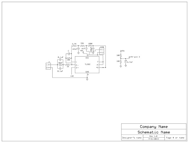
Audio filter in Jota 40 receiver Testing Mode:


Schematic Diagram:


Greetings Everyone,

               We are Happy to share this experiment result of this audio filter. Basically this is not our original design. Our sincere thanks to our good ham friends OH2NLT and OH7V for this beautiful circuit which is used in JUMA Receiver.

                We constructed this circuit in a general purpose PCB for simplicity and also modified the circuit
                 in input side adding some external capacitors to achieve good performance.Half voltage of the
                 given supply voltage is required to the pin no 3.

                 Our testing process begins in the evening tuning for some time no stations heard.After a break
                 we received a strong station with call sign VU2MBU giving General CQ CQ Hi. At the time with
                 out using the filter we heard a lot of  hissing noise in the background.The audio filter is                                    connected in the audio chain suddenly performance increased.Hissing noise level reduced to very
                 minimum SIGNAL to NOISE Ratio improves by 2.5db that is measurable.

                  All components are locally available in Bangalore market for Less than 50Rs/-

                  After this improvement we tested the audio filter continously for 2:30Hrs with the following
                  stations received in good quality audio with less noise.

                   1.VU2MBU
                   2.VU2PLL
                   3.VU2LSR
                   4.VU2KSJ

         Warm Regards,
         RnD TEAM.(MIPL)


Monday, July 1, 2013

WSPR - Successful

Hello Everyone,

We were successful using the WSPR technology to connect with another Amateur Radio Operator.


Our setup consists of a Raspberry Pi (Single Board Computer) as a transmitter. For more information on how to use Raspberry Pi as WSRP Tx., please Click Here

We are transmitting using our Engineers callsign: VU3PWT at 10.14015MHz.

WSPR Tx. info: VU3PWT MK32 25

MK32 is the grid location and 25 is the power in dBm. Tx. Freq: 10.14015MHz

From the Raspberry Pi we connected to a very small amplifier (350mW) and then to a Low Pass Filter which is then connected to a very good antenna.

Using this setup we connected with VK6ZT, Australia. We will be running this setup for some more days to get more propagation signals and more research.

Few pics of the setup:


Friday, June 7, 2013

WSPR (amateur radio software)

Hello Everyone,

Lets check out a new software used the Amateur Radio World. Its called WSPR which is pronounced as WHISPER. The abbreviation of WSPR when expanded is "Weak Signal Propagation Reporter"
Some facts about WSPR
Developer(s)Joe Taylor, K1JT
Initial release2008
Development statusactive
Written inPython (GUI), Fortran, C [1]
Operating systemCross-platform
Available inEnglish, Italian, Spanish, French, German, Japanese, Polish, Portuguese, Russian
TypeAmateur radio and DSP
LicenseGPL
Websitephysics.princeton.edu/pulsar/K1JT/wspr.html
"Courtesy: Wikipedia"


WSPR was developed by Nobel Winning Astrophysicist JOE TAYLOR in 2008 under University of Princeton. 

WSPR is a piece of software that enables you to participate in a world-wide network of low power propagation beacons. It enables your radio transceiver to transmit beacon signals, and to receive beacon signals from similarly-equipped stations in the same amateur band. Participating stations usually upload spots that they receive in real time to a web server, you can find out within seconds of the end of each transmission exactly where and how strongly it was received, and even views the propagation paths on a map.

How to use it:
•       There are two modes
•       Receiving & Transmitting
•       Here we are discussing about Receiving mode

Required things
1. SSB Radio
2. Personal computer with a sound card and WSPR 2.0 software
3. Working Internet connection

How to Listen:
1. Connect SSB Receiver  with sound card
2. Connect PC with internet and sync the internet time
3. Run the WSPR 2.0
4. Select receive mode
5. Wait for even minutes and identify the signals in waterfall display

Format of Data:
 After receiving the signal, WSPR software will decode it and will display the data
1. Call sign
2. Location of transmitter
3. Power used for transmission
4. After reception WSPR software will upload the location in to WSPRnet server and it will generate a MAP

Technical Specification:
•       1. Modulation used : Continuous FSK
•       2. Channel Bandwidth : 6Hz
•       3. Baud Rate : 1.4648 bauds
•       4. Total time taken for transmission 1.54 minutes
•       5. Length of data send over channel : 50bits
•       6. 28 bits for call sign
•       7. 15 bits for location
•       8. 7 bits for power in dbm


Arduino: Temperature Sensor LM35

Greeting Everyone,

Let us revisit Arduino and make a silly project. A very simple one day project using LM35 temperature sensor and an LCD display to show the temperature. The LM35 can be used to sense temperature from -55 Celsius to +150 Celsius. The data sheet can be downloaded from this link: Click Here

What would you need for the project:
1.) Arduino Uno (PC with cable and setup necessary)
2.) LCD display
3.) LM35 Temperature Sensor
4.) Wires

The figure below shows the basic setup and connections:
Here is the code:
For downloading the code please Click Here.
 

#include <LiquidCrystal.h>            // include the LCD driver library  
                                      // declare variables  
 float tempC = 0;                     // Variable for holding Celcius temp (floating for decimal points precision)  
 float tempf = 0;                     // variable for holding Fareghneit temp  
 int tempPin = 0;                     // Declaring the Analog input to be 0 (A0) of Arduino board.  
 float samples[8];                    // Array to hold 8 samples for Average temp calculation  
 float maxi = 0,mini = 100;           // Max/Min temperature variables with initial values. LM35 in simple setup only measures Temp above 0.  
 int i;  
 LiquidCrystal lcd(12, 11, 5, 4, 3, 2); // initialize the library with the numbers of the interface pins  
 void setup()  
 {  
 pinMode(9, OUTPUT);   
 analogWrite(9, 45);  
 lcd.begin(16, 2);                    // Set up the LCD's number of columns and rows:  
 lcd.setCursor(6, 0);                 // Set LCD cursor position (column, row)  
 lcd.print("RnD's");                  // Print text to LCD  
 lcd.setCursor(3, 1);                 // Set LCD cursor position (column,row)   
 lcd.print("Thermometer");            // Print text to LCD  
 delay(5000);                         // Delay to read text  
 lcd.clear();                         // Clear the display  
 }  
 void loop()  
 {                                    // Start of calculations FOR loop.  
 for(i = 0;i<=7;i++){                 // gets 8 samples of temperature  
 samples[i] = ( 5 * analogRead(tempPin) * 100.0) / 1024.0;  
                                     // conversion math of LM35 sample to readable temperature and stores result to samples array.   
                                     // 5v is the supply volts of LM35. Change appropriatelly to have correct measurement. My case is 4.4Volts.  
                                     // If powered from USB then use value 4.4v to 4.6v. If power is 7v< to the Arduino then use 4.9v to 5.1v                                  
                                     // The voltage is critical for accurate readings  
                                     // ( LCD note: line 1 is the second row, since counting begins with 0):  
 lcd.setCursor(0, 0);                // Set LCD cursor position (column 0, row 0)  
 lcd.print("Current Temp is: ");     // Print text to LCD  
 lcd.setCursor(1, 1);                // Set LCD cursor position (column 1, row 1)  
 lcd.print(" Celcius  ");            // Print text to LCD  
 lcd.setCursor(12, 1);               // Set LCD cursor position (column 12, row 1)  
 lcd.print(samples[i]);              // print current Temp sample to LCD  
 tempC = tempC + samples[i];         // do the addition for average temperature  
 delay(800);                         // wait 800ms  
 }                                   // END of FOR loop  
 tempC = tempC/8.0;                  // calculated the averare of 8 samples in Celcius  
 tempf = (tempC * 9)/ 5 + 32;        // converts to fahrenhei  
 if(tempC > maxi) {maxi = tempC;}    // set max temperature  
 if(tempC < mini) {mini = tempC;}    // set min temperature  
 tempC = 0;                          // Set tempC to 0 so calculations can be done again  
 }  


Thursday, June 6, 2013

64 WATTS AMPLIFIER


Greetings Everyone,

               Today we tested an RF Amplifier constructed on a 6.3mm copper plate with dimension of 175X150. Continuous output measured in our standard HP RCT for more than 5 minutes like FM..This copper plate RF amplifier added with extra heat sink for better dissipation.

Tested Frequency-  14MHz.
Continuous Power- 64 Watts For more than 5 minutes.
Transistors            - 2+2 IRF510

Regards,
R&D Team.


RF AMPLIFIER ON COPPER PLATE


Greetings Everyone,

               Today we tested an RF Amplifier constructed on a 6.3mm copper Plate with dimension of 175X150. Continuous output measured in our standard HP RCT for more than 10 minutes like FM. Heat transferring is happened equally in copper because copper is good conductor of heat.

Tested Frequency-  14MHz.
Continuous Power- 35 Watts For more than 10 minutes.
Transistors            - 2+2 IRF510

Regards,
R&D Team.


Tuesday, May 7, 2013

SWR BRIDGE

Greetings Everyone,

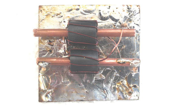
Today we tested a SWR Bridge in our R&D Lab.The SWR Bridge is made by using 6mm toroids winded with 10 turns of 26 SWG copper wire. And also we used 3mm copper tube as shown in figure with wires shorted in two ends. The above circuit is taken from the RF publication issued in 1985. We have only implemented the circuit. The standard SWR's measured are: Zo, Zo/2 and Zo/3.


The below formula is used to measure the SWR:
SWR = (Vforward + Vreverse)/(Vforward - Vreverse)

Schematic diagram is shown below.


 The Results are satisfactory with 7,10 &14MHz Frequencies.

Tuesday, April 16, 2013

13.56MHz ISM BAND AMPLIFIER USING 7NK30Z

Greetings Everyone,

Today we tested an ISM Band amplifier of 13.56 MHz with our standard R.C.T. ,Oscilloscope & Bird 500 Watts Dummy Load. It draws 10A at 33V D.C. That is 330W input and output of 200W. Upon calculating the efficiency more than 60%.

This time we have used a different MOSFET: STP 7NK30Z.  It can withstand up to 7A and maximum voltage of 300V. 7N stands for 7A rating and 30Z for 300V.  


BIRD's 8325 Tenuline Coaxial Attenuator

Greeting's,

First feast your eyes on the pictures below before I explain what this monster machine is.


This is a monstrous 500W, 50 Ohms, 30 dB Attenuator. We got this unit for testing our RF Amplifiers.

The following the specifications for the unit:

Impedance: 50 ohms nominal
Connectors
                  Input    : Bird “QC”, Female N normally supplied
                  Output : Bird “QC”, Female N normally supplied
Power Rating: 500W
Frequency Range: 500 MHz
Attenuation: 30 db ± ½ db, dc-500 MHz
Cooling Method: Dielectric and air convection currents

The Attenuator was tested with our amplifier and we are were exceptionally happy with the results.

The manual for the above unit can be downloaded for further reference from this link: Click Here. 


Friday, April 5, 2013

50 WATTS @ 12VOLTS HF AMPLIFIER USING 16NF06

Greetings to Every one,

We tested another one amplifier in our R&D Lab using 16NF06 mosfet.The results in 14MHz are amazing.We measured 50 watts output in 14MHz and more than 50 Watts in 7MHz using standard test Equipments HP 8920A RCT and GW-INSTEK 30MHz oscilloscope.It drawns 6Amp at 13.8VDC.The efficiency of this amplifier is 60%.  Below is the Photo and circuit details.


Note: T.S Means test select to adjust Minimum 10ma current in each MosFet.

1.) Input Transformer:


This is a step-down transformer. Primary is 4-Turns and secondary is 2-Turns wound on a TV balun core because maximum input power is 5 Watts only 26 SWG is sufficient. We have used 4-Turns primary with 26 SWG and 2-Turns secondary using 24 SWG.

2.) OUTPUT TRANSFORMER:


3.) Output Transformer:

This transformer was constructed using reference from Motorola book (R.F. Device Data -Vol. 2)
Primary consists of single turn copper tube of 4 mm diameter. Secondary consists of 2-Turns of Teflon coated wire.

Here we can see the copper tubes are shorted at one side. TV balun cores are slipped over the  copper tubes and secondary winding is completed last. The primary inductance of one turn copper tube should be 1uH. If the inductance is higher, this amplifier can works at lower frequencies. 

The above picture shows the PCB used to short the two copper tubes.

Here we can see the balun cores slipped over copper tubes.

Regards and Nice Home brewing,
R&D TEAM.


Friday, March 29, 2013

H-Bridge Motor Driver using MOSFET's and Transistors

In this post, we shall be covering on how to construct a H-Bridge Motor Driver circuit using simple MOSFET's and Transistors. The main feature of this H-Bridge is that the motor can be driven in both directions.  

An H-bridge is a circuit that allows a voltage to be applied across any load, like a motor in our experiment, in dual directions. The 'H' here just represents the formation of the circuit and has no reference to anyone.

 The H-Bridge can be realized using simple switches first:-

The H-bridge arrangement is generally used to reverse the polarity of the motor and to let the motor 'free run' to a stop, as the motor is effectively disconnected from the circuit. The following table summarizes operation, with S1-S4 corresponding to the diagram above.

S1S2S3S4Result
1001Motor moves right
0110Motor moves left
0000Motor free runs


 Now let us realize the actual circuit using MOSFET and Transistors:

 To download Schematic: Click Here (JPEG) & Click Here (PDF) 

We have used IRF9540 for P-Channel MOSFET and IRF510 for N-Channel MOSFET. Respective NPN and PNP Transistors are used to drive the MOSFET's which can be seen in the circuit diagram. We have used Arduino to give the logic signals to the pins to turn on and off the MOSFET's. The diodes are provided to prevent back EMF generated by the motor

Direction 1:
Pin1: Logic 1
Pin2: Logic 1
Pin3: Logic 0
Pin4: Logic 0

Direction 2:
Pin1: Logic 0
Pin2: Logic 0
Pin3: Logic 1
Pin4: Logic 1

After reading the above, you  might be wondering why not short the respective PIN's with the same logic. Well you can, that's what we have implemented and its easier to drive the motor in both directions with using only two I/O pins from the Arduino.


 This is the implemented circuit tested in our RnD lab. Below you can see the Working video.
   

Now you can view the motor in slow motion: