Thursday, March 21, 2013

L.P.F. (Low Pass Filter) for 40 Meter R.F. Systems

Greeting Everyone!!!!!!!!!!!!!

We built a L.P.F. (Low Pass Filter) design published in 1987 ARRL  hand-book in chapter 2 (2-44).
The circuit performs very well in 7Mhz freqency. The ARRL Hand-book has given the test chart as below:

Filter No.
Fco
3 dB
20 dB
40 dB
Max. SWR
C1, C5 (pF)
L2, L4 (uH)
C3
(pF)
87
7.54MHz
8.61
11.5
17.0
1.327
470
1.45
820

This filter works as it is with out any changes and modifications.

Below we have show the tested circuit without any modifications from the original circuit which is also show below.


Wednesday, March 20, 2013

Hyper Terminal using MAX 485


Good evening,

If you want to learn how to run a keyboard and PC with a microcontroller by using the MAX 485. I did a small project (Hyper Terminal using MAX 485). In which the data can be transmitted to the PC through the serial port.

The block diagram of hyper terminal using MAX 485 is given below.


For this we are using a PIC 16F877A with a 4 MHz crystal for oscillating and MAX 485, Since the MAX 485 is to be communicating with the PC, The serial port operates at 12 V, which will fry our MAX 485. To fix this problem we are using MAX 232 as a level convertor. The input of the RS 232 must be TTL or C MOS, so we are using two MAX 485’s. Output Of first MAX 485 is differential output, which is converted to TTL output by using another MAX 485. The signal is feed to PC through the RS 232

The schematic of the Hyper Terminal using MAX 485 is shown below:


The full part list of above circuit is given below:
  •  PIC16F877A                                              
  •  4Mhz crystal                              
  • DB9 connector(female)          
  • DB Hood                               
  • MAX232                              
  • MAX485                                   2                               
  • Capacitor(.01uf)                         2               
  • Capacitor (22pf)                         2
  • Capacitor   (1uf)                         4
  • Capacitor (10uf)                         2
  • Resistors (4.7K)                         7 


UART:

Pic 16F877A has UART (Universal Asynchronous Receiver Transmitter) is one of the basic interfaces which provide a simple and reliable communication between one controller to another controller or between a controller and PC.

Interfacing UART with PIC16F877A

Now we want to display a text in PC from PIC16F877A by using UART module. In PIC16F877A contains a single serial interface that is UART. The Transmitter pins send the data into PC and the receiver pin receives the data from PC. The PC and microcontroller speed are denoted by using baud rate. When the baud rates of both PC and Microcontroller are same, then only the data transmit and receive correctly otherwise not. The TXD (Pin 25) & RXD (pin 26) pins are used for data transmission and receive operation. The UART is initialized and set to 19200 Baud rate, 8 bit, no parity and 1 stop bit. Make sure that the PC settings is also the same

processor pic16f877a
include <p16f877a.inc>
__config _LVP_OFF & _XT_OSC & _WDT_OFF & _PWRTE_ON & _CP_OFF &           _DEBUG_OFF


org 0x00
nop
nop
nop
nop

org 0x05
movlw 0x07         ;turn off the comparators
movwf CMCON

bcf STATUS,RP1
bsf STATUS,RP0
movlw 0x06         ;make all pins as digital i/o ports
movwf ADCON1

bcf TRISC,6 ;enable the Tx pin by clearing it

movlw 0x0c
movwf SPBRG   ;set the baud rate as 19200

movlw B'00100100'
movwf TXSTA ;

bcf STATUS,RP0
movlw B'10010000'
movwf RCSTA
main
movf PORTA,0         ;read the port A pins
movwf TXREG ;transfer the data into the register
bsf STATUS, RP0
here
btfss TXSTA, TRMT ;check whether data is transmitted to Tx pin
    goto here                         ;if no goto here
    bcf STATUS, RP0
clrf TXREG                 ;clear the register
goto main                 ;repeat the loop
end


Here initializing the PIC is very important. For UART turn OFF the comparator and make all analog ports as digital port by the using the register ADCON1.make sure that the PORTC TX pin is low and Rx pin to high for data transmission and receive. The baud rate is selected by SPBRG resister.
The TSR plays a major role in data transmission. The read data from the PORT A is send to the TXREG by using the software. Once the data was send to MAX 485 the TRMT bit will be set. Unless the data is not sent the TRMT bit is zero.
The input is given through the switches, the binary value is given as input which is displayed in the PC as a ASCII value
For example
When the input is: 00111101
The output is:         9
Similarly to get the different output varies the input binary value by switching ON & OFF of Port A input pins.   


Wednesday, March 13, 2013

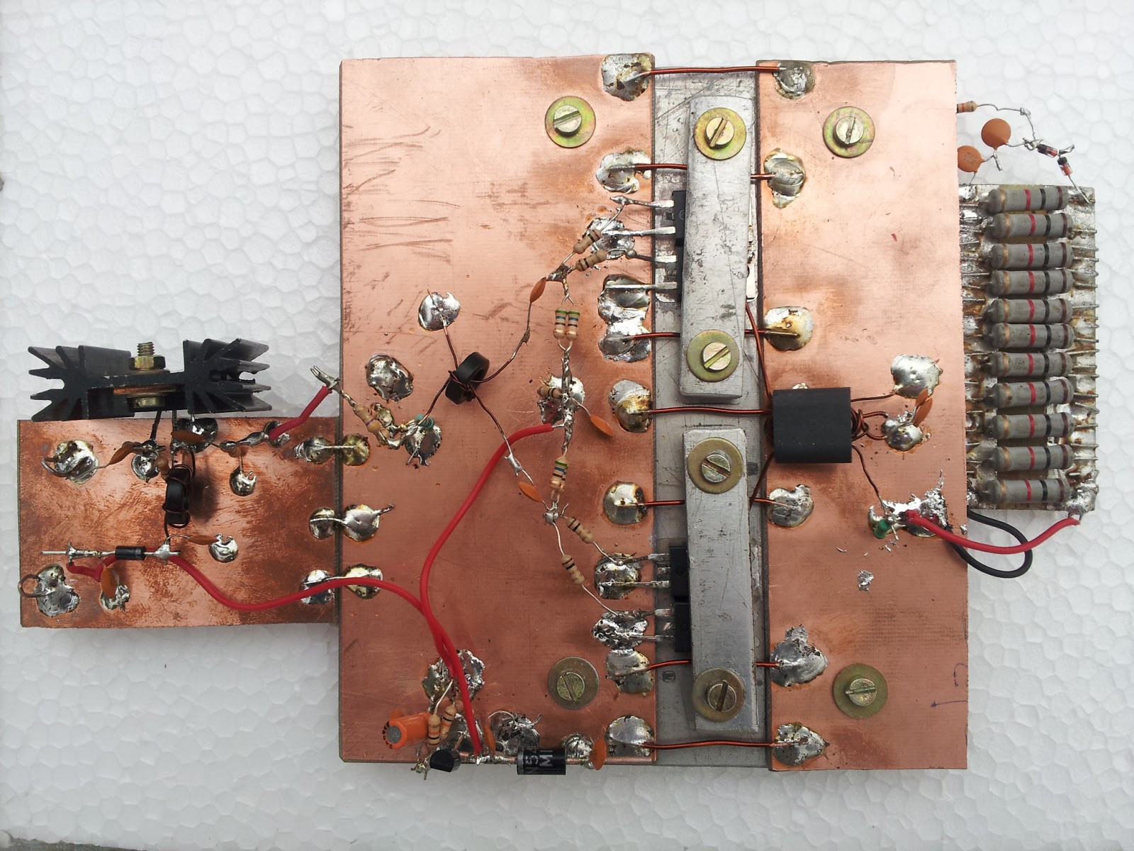
250 WATTS PUSHPULL RF AMPLIFIER


    Dear all,

               We are very happy to share this experimental result. That is we tested a 250watts rf amplifier in     our R&D lab.This amplifier is made with 10nos of  irf 510 mosfets. .Due to insufficient
power supply we got 150 watts only at 29volt 9ampere DC.  The rf input is 5Watts at 13.56MHz ISM band. We need 33volts at 15amperes and we are awaiting this power supply. Final result  and brief about this we shall publish after testing with  high voltage and high current power supply.

Regards
R&D team.

Saturday, March 2, 2013

160 WATTS RF DUMMY LOAD

A 160 Watt RF Dummy Load was assembled and tested in our RnD Lab.
The Dummy Load consists of 80 No.s of 1K Ohm, 2 Watt Resistor's in Parallel and Series combination  to get a total of 50 Ohms.


The total resistance was 49.1 Ohms. After 40 minutes with 30 V, 600 mA with resistance measured was 48.7 Ohms. 


Tuesday, February 26, 2013

25WATT - RF DUMMY LOAD

Greetings Everyone,

A rugged  RF load - Dummy Load was tested in our RnD lab. Normally we use 20 No.s of  1K Resistors in parallel to make the RF load, it gets extremely hot while testing. In this circuit we are using a attenuator type of arrangement to equally dissipate the power. Resistors used is 2 watts rating but suspiciously seems to be 1 watt only. Circuit is given below:


TEST RESULTS:
Tested the RF dummy load with 33 Volt D.C. at 600 mA Current for 1 hour. The resistor value changes from 49.7 to 48.9 which is really good in performance.


The picture below is the one before etching:


Saturday, February 23, 2013

Ardunio - Silly Ohm Meter

Good Afternoon Everyone,

Well, our recent fever in Arduino is cracking up with silly projects. Although I have used it for many years now, the introduction to a new budding Engineer is always intriguing. The Arduino main site many simple and silly projects and tutorials to play and study. After going through some site, we found that something as simple and silly such as Ohm Meter, Voltmeter and Ammeter were not really covered. It may sound quite silly but for new aspirants its something new to learn.

So, getting back to the silly ohm meter, the setup is quite simple. Arduino has a very interesting way to display circuits in a picture manner. Hence, we would like to follow the same. Here is the wiring of the silly ohm meter.


Just a simple project that calculates the resistance of a resistor.  The circuit is based on a simple voltage divider.  First, a wire is connected from the 5V pin on the Arduino to the breadboard +5V bus. Then, another wire connects the Gnd pin on the Arduino to the GND bus on the breadboard.  

Now that you have power, put two resistors in series.  One should be your “known” resistance, we have used a 10K ohm resistor.  The other is the “unknown” resistor that we are trying to find the resistance.  In between these two resistors, another wire should be connected to one of the analogue pins on the Arduino, here we have used the Analog 0 pin.

Here is the Arduino code which calculates the unknown resistance, and outputs it to Serial Monitor on the Sketch program:
 
 //Silly Ohm Meter - RnD LAB's

 int aPinIn = 0;             // Analogue Input on Arduino  
 int val = 0;               // The raw analogue value  
 float Vout = 0.0;          // Voltage at point between resistors (relative to ground)                  
 float Vin = 5.0;           // Vcc (5 Volts)     
 float Rknown = 10000.0;    // The known resistor (10 kohms)   
 float Runknown = 0.0;  
    
 void setup(){  
    
  Serial.begin(9600);  
  digitalWrite(13, HIGH);  
    
 }  
    
 void loop(){  
    
  val = analogRead(aPinIn);           // Read in val (0-1023)  
  Vout = (Vin/1024.0) * float(val);   // Convert to voltage  
  Runknown = Rknown*((Vin/Vout) - 1); // Calculate Runknown  
    
  Serial.print("Vout: ");  
  Serial.println(Vout);               // Output everything  
  Serial.print("R: ");  
  Serial.println(Runknown);  
    
  delay(1000);                        // Delay for readability  
    
 }  


Saturday, February 16, 2013

Arduino Fever

Greeting Everyone,

We recently conducted an introductory presentation on Arduino in SRJC College, Bangalore.

We have generally seen many people hesitating to use Microcontroller's as the complexity is large. Rather a sterotype myth has been created that one should know C-Language to program a Microcontroller and also study the architecture of the microcontroller in order to use it for basic purpose.

Hence many hobbyist, enthusiasts and thinkers have been withdrawn from implementing great ideas. Well lets bust that myth with the introduction of Arduino. The boards are developed such that the common board serves as a development board as well as a programmer. The board is quite cost effective and a very good method to adopt microcontrollers in hobbies, projects and everyday scenarios.

Homepage: www.arduino.cc

A short video of the presentation and the PPT is given below:-


Presentation: Click Here (PPT)

Tuesday, February 12, 2013

Loop Skywire Antenna

Good Morning and Season Greetings.

We setup an antenna in Jyothi Nivas College for the students who had recently participated in the workshop.

A Loop Skywire antenna was setup in the premises. The college had a good open area on the terrace with some building surrounding. We first constructed a base made of car tyre rims, which were welded with 2 feet of 3 inch diameter  poles. Later a 10 feet of 2.5 inch diameter poles were erected on four sides. Couple of concrete blocks were placed on the tyre bases for providing some stability.

Below is the sketch of the Loop Skywire.


Few calculations:

Length of the Antenna wire in feet is given by L(Total) = 1005/Freq.

Where, Freq. is measured in MHz and here we have taken 7MHz, so as per the calculation L(Total) = 144 Feet (approximated to the nearest value). So, each side of the the antenna is given by L(Total)/4 = 36 Feet.

Once the antenna was setup, we tested the antenna performance with a commercial HF rig. Sudhindra, VU3PWT was able to make receive stations from Spain, Tokyo and Northern India(New Delhi).


Friday, February 8, 2013

RF Amplifier using IRF510

Greetings Everyone,

Our old man Marcus,VU2VTM, has a golden principle of making any prototype more than once. And as a strong believer of the golden rule, we at RnD Labs have been playing around with RF Amplifiers a lot lately.

We had earlier made a RF Amplifier using IRF510. Again today we made yet another amplifier using the IRF510. Both the amplifiers are giving the same results and performance.

More details and description will be posted later once the complete analysis as been made.

Version 2
The earlier version is shown below:
Version 1

Tuesday, February 5, 2013

WIDE BAND RF POWER AMPILIFIER USING RD16HHF1


This RD16HHF1 pushpull amplifier specially designed for two band transceiver project.The circuit diagram is mentioned below.This amplifier uses pushpull configuration technique.

Advantages of pushpull amplifier
1.Low distortion.
2.High efficiency.
3.High power output.

FUNCTION:

Operating voltage of this wide band amplifier is 13.8volt dc
Each transistor is biased to draw 400ma without feeding input signal

In this pushpull amplifier two output devices operate in antiphase(ie180deg apart.)The two anti phase outputs are connectedto a load in a way that causes the signal outputs to be added.

This circuit consists of an (input 0-180deg) power splitter driving two identical devices in antiphaseand a (0-180deg) output power combiner adding the output of the two devices in the amplifier load. Splitting is done through the input coupling transformer T1. When Q1 is driven positive using the first half of its input signal the drain current of Q1 increases. At the same time Q2 is driven negative using the first half of its input signal and drain current of Q2 decreases.  Each transistor produces one half of an ac.

The transformer combines the two outputs to form full ac cycle. As a result an amplified version of input signal obtained in the transformer secondary.

Biasing in this circuit is given using the 5volt regulator through the resistor networks to the gate of the transistor.

REQUIRED POWER IS 5WATTS (AVERAGE), 10 WATTS PEP

TEST RESULTS:
4MHz - 16 watts average
7MHz - 14 watts  average
14MHz-12 watts average


TRANSFORMER DETAILS:

T1-4TURNS BIFILAR 26SWG ON 10MM TORROID
T2-3TURNS BIFILAR 26SWG ON 10MM TORROID
T3-3TURNS TRIFILAR ON 10MM TORROID
PRI- 20SWG
SEC-22SWG