It is a simple DC to DC converter. The input is from two
solar panel with minimum Voltage of 24V, typical voltage of 32V and maximum
Voltage 40V.The Output current is 10A @13V.This seem to be highly efficient. No
heat sinks are used for the MOSFET and diodes. Only 3mm thick aluminium sheet
is used for front panel on which power devices are mounted. We tested it for 2
hrs with output current of 4 A @ 13V, the temperature of front panes raises
only by 2 degrees Celsius. For other
details please feel to contact us.
Wednesday, February 5, 2014
Tuesday, January 7, 2014
RMS Antenna
This is a two band antenna working on 20mtr and 40mtr Amateur
Radio bands.
The two band antenna (20m
and 40m) radiating elements are fed on the single coaxial cable and the plastic spreader are shown in the
below figure .
Two 34 Feet long wires are taken for the 40m antenna and two 17 Feet long wires for 20m antenna. Both the
live wires are joined at the connector hot end and the return wires are soldered to the ground terminal of connector. The 40m and 20m radiating wires are
separated by the insulating material. Here we have used the plastic spreader of
length 5.5 Inch.
After erecting the antenna the radiator wire length need to
be adjusted for best SWR. Typically 1.2:1 is achievable.
We will be adding photos soon after tuning.
Saturday, January 4, 2014
SMPS 14V@20A
SMPS (Switch Mode Power Supply) is an electronic power supply. These are classified into four types based on the input and output voltages.
• DC to DC
• AC to DC
• AC to AC
• DC to AC
In this post we will concentrate only on AC to DC (also called off-line DC power supply) converter. The input voltage is normal AC mains and the output rating is 14V@20A. The main blocks in this SMPS are Controller card and Switching Circuit . The functionality of the card is to Sense the output Voltage and Current. We used N-Channel Power MOSFETS (IRFP460) for Switching purpose. It has HY3845 which is fixed frequency current mode PWM controller.
The preview of controller card schematic and image is given below:-
a. Schematic of Controller Card
B. Picture of Controller card
Pictures of the SMPS is given below:-
This power supply can also be used for SSB Transmitter.
We shall keep updating the post for more information. Suggestions are most welcome.
• DC to DC
• AC to DC
• AC to AC
• DC to AC
In this post we will concentrate only on AC to DC (also called off-line DC power supply) converter. The input voltage is normal AC mains and the output rating is 14V@20A. The main blocks in this SMPS are Controller card and Switching Circuit . The functionality of the card is to Sense the output Voltage and Current. We used N-Channel Power MOSFETS (IRFP460) for Switching purpose. It has HY3845 which is fixed frequency current mode PWM controller.
The preview of controller card schematic and image is given below:-
a. Schematic of Controller Card
B. Picture of Controller card
Pictures of the SMPS is given below:-
This power supply can also be used for SSB Transmitter.
We shall keep updating the post for more information. Suggestions are most welcome.
Tuesday, December 31, 2013
RF AMPLIFIER 16NF06
Happy New Year Greetings to Every One,
Today we tested an RF amplifier with 16NF06 mosfet the performance is really superior than IRF510. Normally we used to set 3.3 volts bias for IRF510 but this mosfet requires some more bias to conduct 3.9 Volts. This amplifier drawns 2.1 ampere at 13.8 volts. Output RF power is 25W PEP with 0dbm INPUT.
Instruments used:
1. Standard HP RCT 8900A.
2. 30 Mhz GW INSTEK oscilloscope.
3. Power supply 10 AMP Range.
Regards,
R&D Team.
Thursday, November 14, 2013
SB-7 TRANSCEIVER RX BOARD FULLY ASSEMBLED AND TESTED
ASSEMBLED SB-7 RX BOARD:
BACK SIDE VIEW RX-BOARD WITH SURFACE MOUNT COMPONENTS:
Dear all,
We are happy to announce that our SB-7 Rx Board is fully assembled and tested in our R&D Lab.The performance was really good comparing to previous receivers.The A.G.C circuit and audio filter is doing the job very good. Noise level is less. We heard lot of dx stations in 40 meter. All tests are done with standard HP 8920A RCT and oscilloscope. Signal level feeded and checked from -107dbm to -67dbm. Sensitivity and gain is good.
Regards,
R&D Team.
Thursday, November 7, 2013
SB-7 TRANSCEIVER RF AMPLIFIER SCHEMATIC
RF AMPLIFIER SCHEMATIC:
RF AMPLIFIER COMPONENT SIDE LAYOUT:
RF AMPLIFIER SOLDER SIDE LAYOUT:
FUNCTIONAL DIAGRAM:
Dear all,
I would like to share the RF amplifier schematic of our SB-7 Transceiver project. This is an simple RF amplifier which amplifies the 1 Volt RF to 12 to 15 watts RF Power (PEP). This circuit uses simple transistors & Mosfets. Biasing is made using a 7808 voltage regulator with 10 K POT control. Low pass filter is used in the final stage to eliminate the unwanted signals. The PCB Size is 145 X 73mm.
Regards,
R&D team.
Monday, October 28, 2013
SB-7 TRANSCEIVER TX SCHEMATIC
SB-7 TX SCHEMATIC:
SB-7 TX SOLDER SIDE:
SB-7 TX SILK SCREEN:
SB-7 TX COMPONENTS LAYOUT:
Greetings Every one.
I would like to share the TX side of our SB-7 Transceiver Project. This circuit is simple and straight forward.
1. It uses TLO82A as mike amplifier.
2. Double balanced mixers using diodes.
3. If Amplifier.
4. 12 MHz crystals for Ladder Filter.
5 . Broad Band Amplifier
FUNCTIONAL DIAGRAM:
Regards,
R&D Team.
Monday, October 7, 2013
SB-7 SINGLE BAND TRANSCEIVER 7MHz
I would like to share some inside views and also like to have some critics to comment on our new upcoming project SB-7 Transceiver which is a single band 40 meter transceiver in S.S.B. mode (LSB only).
A small preview of the schematics and components used have been shown below:
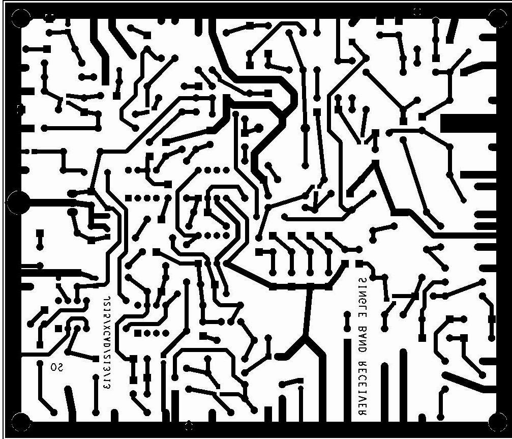
SINGLE BAND RX SCHEMATIC:
Wednesday, July 31, 2013
AUDIO FILTER
Audio filter in Jota 40 receiver Testing Mode:
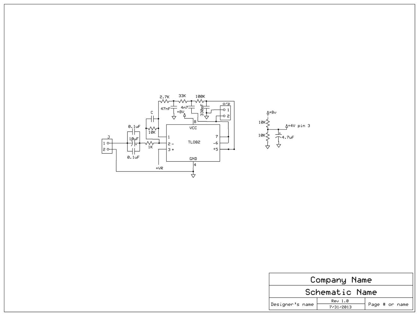
Schematic Diagram:
We are Happy to share this experiment result of this audio filter. Basically this is not our original design. Our sincere thanks to our good ham friends OH2NLT and OH7V for this beautiful circuit which is used in JUMA Receiver.
We constructed this circuit in a general purpose PCB for simplicity and also modified the circuit
in input side adding some external capacitors to achieve good performance.Half voltage of the
given supply voltage is required to the pin no 3.
Our testing process begins in the evening tuning for some time no stations heard.After a break
we received a strong station with call sign VU2MBU giving General CQ CQ Hi. At the time with
out using the filter we heard a lot of hissing noise in the background.The audio filter is connected in the audio chain suddenly performance increased.Hissing noise level reduced to very
minimum SIGNAL to NOISE Ratio improves by 2.5db that is measurable.
All components are locally available in Bangalore market for Less than 50Rs/-
After this improvement we tested the audio filter continously for 2:30Hrs with the following
stations received in good quality audio with less noise.
1.VU2MBU
2.VU2PLL
3.VU2LSR
4.VU2KSJ
Warm Regards,
RnD TEAM.(MIPL)
Monday, July 1, 2013
WSPR - Successful
Hello Everyone,
We were successful using the WSPR technology to connect with another Amateur Radio Operator.
Our setup consists of a Raspberry Pi (Single Board Computer) as a transmitter. For more information on how to use Raspberry Pi as WSRP Tx., please Click Here
We are transmitting using our Engineers callsign: VU3PWT at 10.14015MHz.
WSPR Tx. info: VU3PWT MK32 25
MK32 is the grid location and 25 is the power in dBm. Tx. Freq: 10.14015MHz
From the Raspberry Pi we connected to a very small amplifier (350mW) and then to a Low Pass Filter which is then connected to a very good antenna.
Using this setup we connected with VK6ZT, Australia. We will be running this setup for some more days to get more propagation signals and more research.
Few pics of the setup:
We were successful using the WSPR technology to connect with another Amateur Radio Operator.
Our setup consists of a Raspberry Pi (Single Board Computer) as a transmitter. For more information on how to use Raspberry Pi as WSRP Tx., please Click Here
We are transmitting using our Engineers callsign: VU3PWT at 10.14015MHz.
WSPR Tx. info: VU3PWT MK32 25
MK32 is the grid location and 25 is the power in dBm. Tx. Freq: 10.14015MHz
From the Raspberry Pi we connected to a very small amplifier (350mW) and then to a Low Pass Filter which is then connected to a very good antenna.
Using this setup we connected with VK6ZT, Australia. We will be running this setup for some more days to get more propagation signals and more research.
Few pics of the setup:
Subscribe to:
Posts (Atom)