
We have
tested the DC DC converter in field yesterday in SALEM. The two units are
working more satisfactorily than we expected. We connected two solar panels of
100Watt in series to get the 40Volts on no-load and 36Volts on load (Battery). The
test is continued till the shade falls on the panels at 5:30. For 2hrs the battery
gets fully charged.
Improvements
in the 2nd unit:-
There
was a high frequency humming sound in the transformer. To reduce that we
increased the turns ratio from 7:5 to 8:6. We added two high voltage capacitors
(1000uF & 0.1uF) at the input to remove spikes. We relocated the diode to
improve the heat dissipation. The MOSFET and Diodes are placed in the front and
back panel respectively. The raise in temperature of panels is less than the
previous unit.
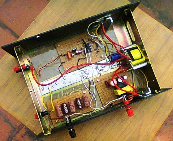
The pictures
of 2nd unit are given below.

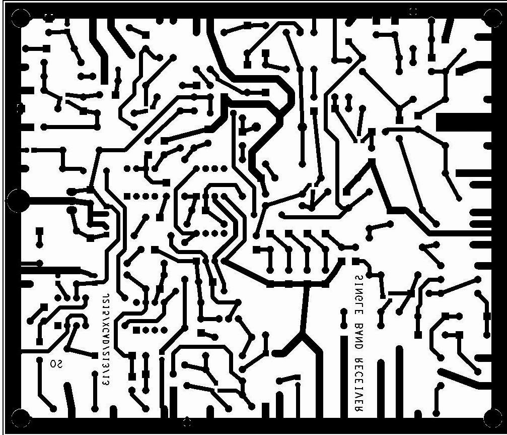
The schematic
diagram is shown below.

For more details please feel free to contact us.


